"Building in Style"

"Building in Style"
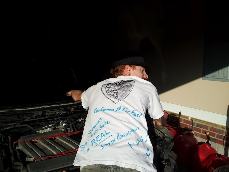
Donations for the REAL Smyth shirt are accepted lol

Tuesday, March 26, 2013

Day 23 ~ Shifter box continued

     I got my necessary hardware from the store yesterday, so I'm back in business. The bolts I had were about 30mm long. A 20mm would work, but since they nylon lock nut and an extra washer (provided but not pictured) was used, I went with my 25mm ones. This gave me the needed clearance and kept me from having to turn the nut for all that extra thread. I also took some painstaking time getting the thread rod length adjusted just right.
Supplied bolts are a bit long

At last it doesn't touch any part of the box at any position. Hopefully that will pay off and prevent any future issues. It's really a neat setup with the bell crank reversal. I've seen pics and am wondering if I should add an extra guard underneath to keep any stray rocks, sticks, or other debris from contacting the shifter assembly. I'll let you know what I come up with.

My 25 mm bolts work perfectly now. This is just for reference.
You can see my washer/spacer config is a little different from Smyth, but yours may work perfectly in one or the other.
The important thing is to make sure you have good clearance and smooth operation through the full range.
Take your time with this. It's not something you want to have to redo at the end of the project.
Also, the cover plate only takes a nibble with some tin snips to get a good seal and fit between the bell crank supports.
     Also, the big metal bracket plate Smyth provides, like the windshield frame, is untreated steel. I saw from the pics that he had painted or coated his, so I decided to spray mine with some rubberized undercoating. I bought that can when I had a Jeep in college with some bumper damage from trying to off-road through a small tree that had grown up in one of the trails. It worked great to cover the paint scraping, and its thick texture hid the dimples from my hammering it back into shape. That was probably 12-14 years ago, so I'm surprised the stuff in the can was any good. The spray nozzle was plugged a bit, so I couldn't get a good pattern. I just sprayed it on thick and let it run. Who cares right? It's just there to keep the rust and rocks away underneath the car.
Not a great paint job. Function is adequate underneath though.
RIGHT: Illusion...it's not that big really, just hanging on a garage door rail.
= )

Saturday, March 23, 2013

Day 22 ~ Door cuts, brake line replaced, shifter box work

     Smyth recommends using a circular saw (with metal-cutting blade of course) for the door cuts. This is extremely handy. I probably could think of a few other areas it would have made life so much easier than the reciprocating saw, but especially the doors. It's definitely a lot more dangerous of a tool if it gets caught and you lose control, but proper use and situation awareness can prevent accidents. Other recommendations I'll add are to cut these with the doors installed so they're their own stabilizer, and make sure you have room enough to open the doors fully. That area near the front of the door is the hardest part with all the extra layers, and whatever you can't reach easily with the circular saw, you'll need to finish with the reciprocating saw (which is more tricky and time consuming). It took me a while to finish marking the lines between the dimensions I'd already measured and marked, so between that, the cutting, and a little cleanup, I burned about an hour and a half on the doors.
     Since I had an extra pair of rear brake lines laying on the G3F from another Jetta body, I decided it was time to install that so it wouldn't get bent or damaged just being in my way. If you remember, I had cut the line going to the right rear wheel when I made my rear seat area cut. See notes on that to avoid the same mistake. Otherwise it's likely to cost you more than I because you probably won't have an extra Jetta body sitting there for spare parts.
     Next I unbolted the original shifter box assembly (2 (10mm) nuts in front on top, 2 bolts underneath and to the rear). I gently used some groove joint pliers ("channel locks") to remove the bottom cover by prying each tab. I'd like to keep it in tact to re-install as a dust cover. I think I'll only need to trim the front corners, and drill a drain hole to make it work with the modified box. Getting all the parts sorted out and put together took a lot of time and trial-and-error from the pictures in the build manual. Let me just note here that you really need to peruse the manual by major sections, not step by step. There's a lot of good tips and necessary steps that come later on in the section. If you try to replicate the picture and progress of the first few steps, you'll be ahead of yourself, and will likely have to redo some things based on the notes to follow. Also, I had quite a time with clearances. The end result will work the same, and looks close, but has a couple washers used as spacers in a different area than the one in the manual. NOTE: When you drill out the ball-end on the longer shifter box thread rod, use at least a 9/32" drill bit. A 1/4" will fit over the post tightly and will bind in a Reverse, 1st, or 2nd gear position. I also used a round file to just widen the hole a tiny bit in that direction. NOTE: Also, when you get your hardware, check the length. If it's over 1" long, you'll be better off getting a couple shorter ones as clearances get pretty tight, and there was a ton of thread left out the end from 1/4" to 1/2". I will update the measurements after my trip to Lowe's either tomorrow or Monday. Hopefully, my feedback to Smyth on the different hardware sent vs. pictured will keep you from having anything but the right size anyway. That's what beta is all about ;) working out the little stuff on production.
     Well that's about it for today. I'd have put some pics in, but my camera app is misbehaving lately, crashing and rebooting my device, so I'll get some from another source soon. Have a great day, and thanx for reading! = )

Thursday, March 21, 2013

Day 21 ~ Reinstall doors & mark for cuts

  Title pretty much sums it up. Other than a few miscellaneous things, installing the doors, and following the manual for marking those cuts is really all I got to tonight. Just trying to keep doing something even though I only had an hour today... I'm getting ready for a big weekend, so stay tuned. :)

Wednesday, March 20, 2013

Day 20 ~ Rear tie rods

Another short evening, but I'm itching to get back to work on this baby. I got a box of parts in from Smyth Performance recently which included some miscellaneous hardware that I had been missing and also the shifter kit! This will allow me to do gobs more on the project. I was at a halt on a few areas like the wiring harness extension, fuel-cell and battery box assembly, and "plumbing." I didn't want to run all the front-to-rear hoses and wire without having the shifter kit installed as I would then just have to remove it to give myself working space there in the channel.
   Anyway, tonight I laid out all my parts to get ready to tackle the shifter kit assembly this weekend. That's the big goal, but I'd really like to finish up the last bit of wiring harness extension also. If time is on my side, and I get really zealous, I'll assemble the front hardware for the fuel cell and battery box, do the cut at the base of the windshield frame (dash trough front area), and install the windshield frame. But let's not set the bar too high just yet. It's been a really long time since I've had the opportunity to put my nose to the grindstone here.
   Tonight's work, other than layout and re-familiarization was limited to getting the tie rods removed from my extra power steering assembly, and installing them on the rear subframe. I finally got Evernote installed and synchronized yesterday. Now I can see the latest and greatest notes on everything that's been shared with me so far on the build manual. Mark recommends buying the tie rod parts on ebay, and it's actually not a bad deal. He said $130 or so, but I saw them for $95 w/FREE shipping. I almost bought them anyway, but I have an extra front end or two from my collection of Jetta parts I've been acquiring lately, so I couldn't put some good tie rods to waste. From the pictures, I finally figured out (don't know why I was dense to it before) how to remove the tie rods from the power steering piston rod. Having had a difficult time removing these, let me suggest that if you're also not buying new ones, break the tie rods free before removing the power steering assembly from the K-frame. Having it bolted onto something or in a vise is the way to go with this. It was pretty simple to do as far as complexity, but it was difficult in a few time-eating ways. I don't know if you're reading this, Smyth Performance, but I'm going to make a small beta-suggestion on the subframe. Where the tie rod bolts to the powder-coated frame, the hole was almost perfectly sized, but a tad tight. I had to run a tap through it to get the tie rod stud to pass through. Maybe on some future frames, have it reamed out a couple thousandths (or laser cut a smidge bigger). Not a big deal, just some feedback that may help someone out later on.
   I decided to call it quits early so I could blog and get to bed. It feels good to get back to work out there. This last weekend I had wanted to get some things done on the G3F, but over the winter, my garage shrank, and spring cleaning was obviously necessary. Now I have tons of room to work. Fabulous!

Wednesday, September 19, 2012

Day 19 ~ Rolling Chassis


  Due to the work I need to do to sell my Firebird, I'd like the jacks back. So today I set out to remove the outer CV joints from my old spare set of half shafts. It's pretty simple, just super greasy. The only really tricky part is once you've tapped the end off the splines, getting the balls and cages out. If you like those metal puzzles in Cracker Barrel, then you'll get them out fine. No matter. I got them both cleaned up and installed in the front hubs. This is important for support of the bearings. Do not ever load weight on the wheels without these in place as damage to the bearing will likely result. Well enough about that. I threw the old wheels on and lowered her down...
   Woohoo! It looks pretty sweet sitting nice and low. Clearance is pretty tight on stock offset to the new struts. Looks pretty good now, but I'll be getting the aftermarket wheels on eventually anyway.
  Well, a short night relatively, but some progress, answers from Mark, and preparation for several other big things going on around here this weekend means I'm plenty satisfied with today's work. Peace out!

Tuesday, September 11, 2012

Day 18 ~ Rear K frame & suspension

  Almost have a rolling frame! In fact I almost went ahead and bolted the wheels on just for fun to get the G3F off the jacks tonight, but in lieu of needing to hook up the rear calipers, rotors, brake lines, and tie rods, I figured it would just waste time for an appearance. The tie rods that are stock have ball ends in the power steering boots and threaded portions (14mm) at the outside ends. I unscrewed the rods to remove the power steering assembly (4 bolts) from the K frame.

  Taking up the most time tonight was the strut assemblies' replacements. You would think with all the practice that this would have been easy by now. Not really. Even after replacing the front suspension in my TDI this week, I still had plenty of difficulty getting those spindles loose. There's a tool on ebay ($19.99 free shipping: search "vw suspension tool"), and a set on amazon ($60ish) that looks like a socket with a flat tip screwdriver bit in the end. They're not really expensive, so I highly recommend purchasing one to do the spreading for you. I also had to burn time filing both of the bottoms of the new struts at the welds. So that's 3 of 4 that wouldn't fit down the spread tube without filing the welds that left a lip just wider than the tube. Maybe I can get Mark to make a quality assurance call to the manufacturer he's getting these from. The welds are nicely done. It's just the really tight tolerances don't leave much margin for any excess material.
See both the tie rod end and the cylinder clamp of the VR6
  NOTE: There is a difference between the TDI and the VR6 spindle where it clamps the bottom of the strut. The VR6 is basically one solid cylinder vs. the TDI which looks the same from the outside, but has two 1/2" bands that contact the strut. I found the VR6 to be much tighter and more of a pain to spread adequately.
Using an extra donor mat to keep scratches away as I drag the rear K frame assembly into place ; )
Hoisted K frame up into place. Nice fit!
  I have a bit of work to do getting the brakes looking nice and being functional, but my biggest hold-up for now on the rear spindles is the tie rod modification. In case you're wondering how we get away with a front (turnable) suspension on the rear, Mark made a place to bolt the tie rods into the tubular subframe to lock the wheels in place and also give a toe adjustment for alignment. My only problem is that we don't use the stock tie rods, but I don't have any hardware that substitutes the tie rod. I'll put that on my list of things to request from Smyth Performance tomorrow when I call. No matter, though, I'm sure he has a little goodies list of things to send me soon. We just want to make sure all the kinks are worked out before production hits. The last estimate I heard on that was the end of this month, but I believe that's optimistic by several months. I'd guess high 80's to 90% completion by this month. There's the finished top to consider, VR6 exhaust and manual tweaking, any 1.8T differences in development, and probably a few more things that need to be buttoned up before a full-scale production operation gets underway. In the mean time, that high percentage of finished items can keep any further buyers busy for quite some time, so no worries here. I've been kind of slow getting to things around here because I'm finding parts I don't yet have are "next" in my assembly, and I've had an overwhelming amount of maintenance and other issues coming up lately. As usual, there's still plenty to keep me busy before I run out of things to do. I plan to get the windshield frame, rear brake lines, rotors, and calipers installed, and put the wheels on the ground next. Then I work on swapping the tranny to the replacement motor, and giving that all a good once-over. Once I remount the engine in the back, I can begin plumbing and routing of all the systems and components. Sounds like fun!

Tuesday, September 4, 2012

Day 17 ~ Wiring 2 and Misc.

  I put in about 2.5 hrs on wire splicing until I ran out of connectors for the larger gauge wires. I got plenty of the small ones, but only half the larger ones I needed in the shipment. I'll make sure there's an inventory adjustment so you won't have to worry about it when you get your kit. Simple fixes . . . beta = )
  After going at it for a long time, I found myself starting to make a couple mistakes, so I took a break from the wiring so as not to mess up something critical. I need some coffee or a Monster energy drink or something to finish up those last couple connector extensions. Still waiting to hear from Mike on a double-check of the VR6 wiring, but I can finish all but the 2-pin connector according to the manual so far. If any other betas working on (or finished with) wiring want to point us in the right direction, what component is the 2-pin extension going to/from? I found 8 identical connectors, of which 3 or 4 could be eliminated, but could use some help figuring out which component I'm running an extension to. We'll get it double checked and clarified in the manual. Other than that, the rest seemed easy to find and extend so far.
   The goal is to get the G3F off the jack stands and onto its own wheels, so I spent some time getting the extra K-frame et al ready for installation. I still have to pull the OEM struts, source some calipers, and figure out the tie-rods and half shafts configuration. Then I'll bolt the frame on, hook up the new struts, and put the wheels back on for "rolling frame" status.
   Sorry about my long silence, last week was spent heavily in dismantling the spare VR6 I bought for the engine. I got that one completely gutted, kept anything usable, and scrapped the rest. Then I cleaned the engine a bit and pulled off anything that was deteriorated or damaged. I'll be dividing some efforts between electrical extensions, suspension installation, and engine preparation until I get some more parts. After that, I expect to fill up the tunnel with heater hoses, shift cables, and all the rest of the plumbing. Seems simple enough, but I'm learning everything is taking longer than I expected. ;)